
2 reasons for electrical fires There are many reasons for electrical fires, such as short circuit, insulation aging, overcurrent, ground fault, poor contact, home appliances or electric heating equipment to ignite combustibles. In essence, in all electrical fire causes, the short-circuit is caused by a short circuit, and 90% of the short-circuit fire is caused by a gradual fault. Gradual faults have a development process, and the ability to release during this process is directly expressed as temperature or arc, which is essentially an increase in leakage current. The development of faults such as overcurrent load, poor contact, home appliances or electric heating equipment is also accompanied by an increase in leakage current. Because the leakage current is relatively small, it is often not enough to make the overcurrent protection device (circuit breaker, fuse) operate. The local high temperature generated by the leakage arc of several hundred milliamperes is more than 2000 °C, which is enough to ignite the surrounding combustibles and cause fire. Concealment often leads to fires.
The cause of such electrical fires is caused by abnormal leakage currents (even small values). It is a hidden fault. If it is not known by certain technical means, the continuous occurrence of the fault may eventually occur. Will cause an electrical fire accident. Therefore, it is necessary to have a device for detecting the residual current (also known as leakage current or leakage current) in the line, which is used to measure the electrical parts in the electrical insulation between the metal parts, or the live parts and the grounding parts. In the meantime, through the current formed by the surrounding medium or the insulating surface, the early warning of such electrical fires can be realized, and the purpose of eliminating fire hazards can be achieved.
3Electrical fire monitoring system The electric fire monitoring system refers to a system that can issue an alarm signal, a control signal and can indicate the alarm location when the detected parameter in the protected line exceeds the alarm set value. The electrical fire monitoring system is a means of electrical fire prevention. It is a real-time monitoring system that acts before the occurrence of electrical fires. It is responsible for the task, function and technical means of the "automatic fire alarm system" after the fire has occurred. All aspects are different, and the two cannot be confused and replaced.
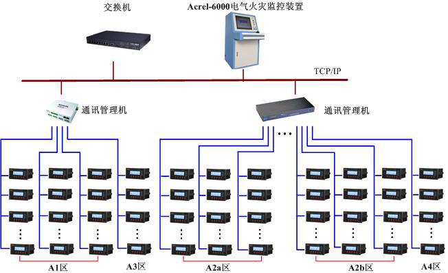
The "ARCM" electrical fire monitoring system is independently developed and produced by Shanghai Ankerui Electric Co., Ltd., including Acrel-6000 electrical fire monitoring system software and ARCM series electrical fire monitoring detectors. It is a new generation of electrical fire monitoring products applied in the dual fields of civil construction and industrial construction. It has the characteristics of ultra-early, high intelligence, miniaturization, multi-function, high reliability, simple and practical. The device is based on a large amount of valuable experience accumulated over the years by the company's system integration projects in the industrial and civil construction fields at home and abroad. The monitoring equipment is designed and developed by industrial computer, has good reliability, and optimizes the human-computer interaction function, making the whole system easy to install, debug and maintain. The host adopts bus data transmission mode and is equipped with residual current type electric fire monitoring. The detectors form a large-capacity electrical fire monitoring system for real-time monitoring and prevention of early electrical fires in high-rise buildings and various industrial sites.
3.1 Basic Principles of Monitoring System The electrical fire monitoring system integrates monitoring, alarming, control and centralized management. The bus is generally connected to a monitoring detector or monitoring unit to communicate with the host and transmit all data collection information. The host collects the received data, monitors the changes of the three-phase current, residual current, temperature, voltage and other parameters of the detected electrical circuit, and feedbacks the current loop status and other information. When an abnormality occurs in the measured line, the electrical fire monitoring detector collects signals through the tools such as transformers and temperature sensors, and sends an alarm signal when the monitored value exceeds the set threshold and reaches the trigger time, and the alarm signal is uploaded to the monitoring device. In the further identification and judgment, the monitoring host issues a fire alarm signal, the alarm indicator lights up, the alarm sounds with a card, and an alarm message is displayed on the display screen, the alarm position is specified, the on-duty personnel quickly perform the inspection process, and the alarm information is sent to the centralized control. At the same time, the duty personnel can also control the equipment to cut off the faulty loop power through the monitoring equipment, and link other fire-fighting equipment to prevent the occurrence of electrical fires.
3.2 The basic components of the monitoring system The electrical fire monitoring system (GB14287) gives the definition and basic components of the electrical fire monitoring system. The electric fire monitoring system is a system that can issue an alarm signal, a control signal and can indicate an alarm part when the detected parameter in the protected line exceeds the alarm set value, and is composed of an electrical fire monitoring device and an electrical fire monitoring detector.
The electrical fire monitoring system developed by Shanghai Anke Rui Electric Co., Ltd. mainly includes: Acrel6000 electrical fire monitoring equipment and ARCM series electrical fire monitoring detectors. Depending on the size of the project, different system solutions are available to achieve better and better goals. Generally we are divided into: small single building; large single building; large group building. The basic system structure diagram for each type of project is given.

4 Precautions 4.1 Applicable to electrical fire monitoring system Distribution system protection grounding form 1) Distribution system grounding form TN system definition: The power system has a little grounding, the exposed conductor of the electrical device is connected to the location through the protection line .
The TN system can be divided into: TN-S system, the neutral line (N line) and the protection line (PE line) of the whole system are separated; in the TN-C system, the neutral line and the protection line of the whole system are unified. In the TN-CS system, a part of the neutral and protection lines in the system are unified.
Definition of TT system: There is a point in the power system that is directly grounded. The exposed conductive part of the electrical device is independent of the power system grounding point through the protective grounding wire.
2) Problems that should be paid attention to in different grounding systems. When installing residual current type electric fire monitoring detectors, N lines and PE lines must be strictly distinguished. Three-wire four-wire or four-pole four-wire type N lines should be connected to residual current mutual inductance. Device. The N wire through the transformer shall not be used as a PE wire. It shall not be grounded repeatedly or the device may be exposed to the conductor.
In the TN system, the TN-C system must be retrofitted to TN-CS, TN-S system or partial TT system before the residual current type electrical fire monitoring detector can be installed. In the TN-CS system, the monitoring detector is only allowed to use a separate part of the N line from the PE line.
4.2 Installation of residual current transformer 1) Residual current transformer threading residual current transformer should distinguish the phase line, N line and PE line in the power grid before threading. The phase line and the N line must pass through the residual current transformer together, and the PE line cannot pass through the transformer. In the system, if the N line does not pass through the transformer together with the phase line, once the three-phase load is unbalanced, a current will flow through the N line, and the detector detects the current signal, that is, a malfunction occurs. The N lines between different circuits are not connected or grounded repeatedly. Otherwise, it will cause malfunction. When the system is running, the leakage current value is too large and an alarm occurs. A large part is caused by such a situation. If the PE line passes through the transformer together with the N line and the phase line, it will also cause the rejection or malfunction of the monitoring detector.
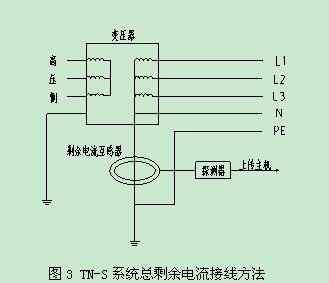
Not all residual current monitoring needs to penetrate the phase line into the transformer. The total residual current monitoring method of the TN-S system can be excluded. It can pass only one cable through the residual current transformer. The advantage of this method is that a small residual current transformer can be used to improve the measurement accuracy; in the later stage, if the transformer fails, the maintenance is convenient. The specific wiring diagram is as follows.
For the protected line as the power line, in order to avoid the large-scale equipment starting instantaneous ground leakage current caused by the device alarm action, the monitoring detector's action time should be extended to avoid the abnormal leakage when the device starts, to prevent malfunction.
Hierarchical protection application principles. System applications often have hierarchical protection, common 2 to 3 levels, the selection principle of the upper and lower levels: in terms of operating current, the setting of the upper device must be at least twice that of the lower device; in terms of the trip time, the delay time of the upper device should be greater than The operating time of the primary residual current protection device, and the difference of the action time shall not be less than 0.2s.
Residual current electrical fire monitoring detectors are generally not used alone, but are used in conjunction with electrical fire monitoring equipment. When a leakage fault occurs, there is no immediate fire. If the power supply of the protected object is automatically cut off when the monitoring detector is protected, it may cause other unpredictable hazards. Therefore, the residual current type electrical fire monitoring detector should be used for alarms, and it is not appropriate to automatically cut off the power. When there is an electrical fire monitoring device, the fault information is reported to the host device, and the attendant confirms the fault information and performs the next operation according to the actual situation.
4.4 Leakage fault check Residual current type electric fire monitoring detectors are generally installed at the outlet end of the power system distribution cabinet (transformation station) or the floor distribution box incoming line. When a fault occurs in a protected line or equipment, the point or location of the specific fault cannot be determined. It is also a cumbersome task to check each line and equipment after the installation point one by one.
First, the cause of the leakage fault is caused by improper wiring or wiring errors, or equipment or line failure or new load. In the new operation project, many cases are caused by improper wiring or wiring errors. At this time, the wiring of the protection circuit needs to be corrected one by one. After the equipment in the protected line is in normal operation, if the residual current value is within the expected range, it can be basically determined that the line is normal. The residual current caused by wiring errors tends to be large.
Secondly, the specific parts of the leakage are detected by means of meter detection method, separate power-off method (one by one elimination method), and power failure measurement method. One of the most effective and convenient methods is the separate power-off method, which can narrow down the fault location one by one and finally find the cause of the fault. In the case that power outages are not allowed, we generally use observation methods and meter measurements. Observing method is mainly to observe whether there is obvious wiring error or arcing phenomenon in the line; in the instrument detection method, we need to have a special hand-held leakage detecting device to detect the size of leakage in each circuit and locate according to the size.
5 Conclusion With the development of China's economy and society, electrical safety has attracted more and more attention, and people have gradually realized that electrical fire monitoring systems play an important role in preventing the occurrence of electrical fires in the early stage. Early countries introduced relevant technical standards to regulate the design and construction of electrical fire monitoring systems, which led to the current chaos in the industry and the system's effects did not achieve the intended purpose. At present, these products have been confirmed to be included in the second batch of fire-fighting products that implement compulsory product certification. They will be included in the national CCC-certified products from January 1, 2013. This shows that the relevant national departments can regulate the quality of such products and market confidence. .
This is the Y81 series scrap Metal Baler that turns over and discharges the bales. Also known as a turn-out BALER. Its function is the same as that of ordinary metal balers, and it can baling and compress various scrap metal materials, including scrap copper, scrap steel, scrap stainless steel, scrap aluminum, scrap iron, etc. Metal scraps are as small as metal shavings, as large as car shells, etc. It is only necessary to customize appropriate bins according to the size of the scrap. There are two ways of discharging, one is to turn the bales out from the side of the material box, and the other is to turn the bales out from the front of the material box. Customers can choose the appropriate discharge form according to their own venues. Our scrap metal balers can be customized according to customer needs.
Turn-out Baler Machine,Metal Baler,Automatic Metal Baler,Metal Press,Baling Press Machine
Jiangsu Dalongkai Technology Co., Ltd. , https://www.dlkscrapbaler.com